
Stair tower is a common service structure that is often provided in process plants that have vertical tower like processing units. The stair tower provides access for both operational control and monitoring, periodic inspection and maintenance of equipment mounted at various levels of the process equipment. The stair tower is usually a lattice frame structure with its independent support system.Since this structure is slender, lateral loads induced by wind or earthquake forces are resisted by tie members at various levels that transfer the force to the building or technological structure for which the stair tower is intended.The case under study is related to the design of a new stair tower for an existing tall equipment structure. The new stair tower base rests on bracket provided on existing equipment structure. The bracket supporting existing beam has enough rigidity to sustain vertical loads from the stair tower but there is a huge difference of wind induced equipment structure sway which induces significant secondary stresses in the stair tower members. The design is intended to carry out a parametric study to determine the most effective arrangement of lateral ties from equipment structure and optimize response of the stair tower with respect to the sway of the existing equipment structure due to wind loads at the various tie in locations.
Introduction
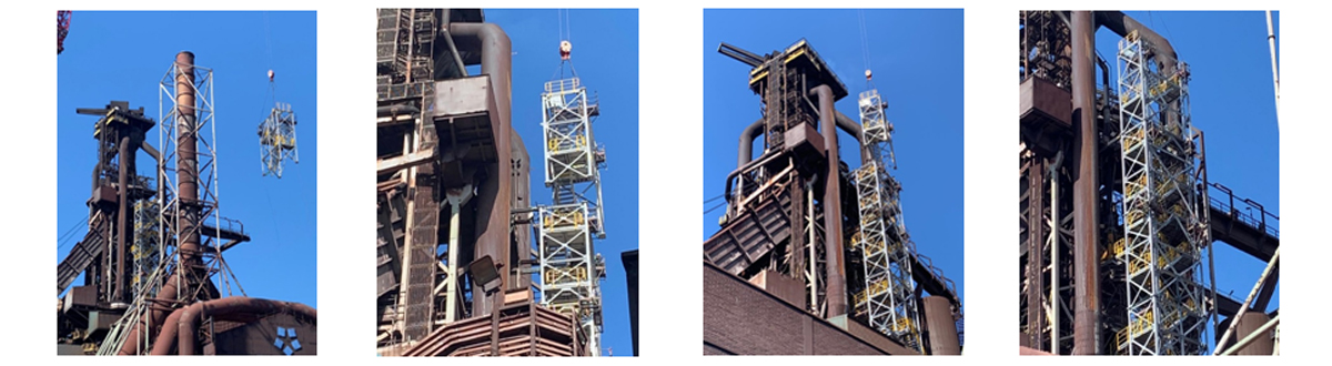
In industrial tall stair towers, lateral loads induced by wind or earthquake forces are often resisted by lateral tie members at various levels that transfer the force to the building or technological structure for which the stair tower is intended. The case under study is related to the design of a new stair tower for an existing Blast Furnace (BF) of an integrated steel plant in Europe. The functional requirement of the stair tower is to provide access to operating platforms at various upper levels of BF structure. Height of the BF structure is 100m and has much higher stiffness compared to the proposed new stair tower. The new stair tower base level is at 50m and rests on a new bracket provided on existing BF structure and the tower rises to 100m level to the top of the BF. The bracket supporting existing beam is having enough rigidity to sustain loads from the stair tower at base level. Between the base level and top level of stair tower, there is a huge difference of wind induced BF structure sway (for 50m height wind drift value is in the range of 350~370mm). This kind of BF structure sway pattern induces significant amount of secondary stresses in the stair tower members. Hence to arrive at the required stiffness of stair tower, so that both the stair tower and the BF structure behave like an integrated structure maintaining economy become challenge for the design engineer.
Modelling of Structure and Design Loads
Stair towers attached with structural building or technological structure are generally analysed by combining the stair tower with the main structure in analytical space frame model. In case of retrofitted stair towers supported on process equipment, as the equipment design is under the scope of equipment vendor, the stair tower needs to be analysed separately. In this case the space frame for the stair tower structure has been modelled in Staad pro software. The process equipment is not modelled but the sway of the equipment is applied as loading at the tie locations for the analysis. Loading has been calculated based on Euro code and the same is applied in the analysis. To include the effect of base level supporting bracket flexibility, the bracket is also integrated with the stair tower analytical model. The details of the structure and bracket support are shown in Fig.-1.
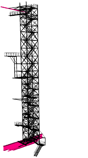
Fig.-1a: Stair Tower structure
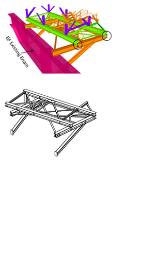
Fig.-1b: Supporting bracket
Boundary condition and Support Definition
Stair tower supporting bracket at base level is supported on an existing BF structure beam. Supports for the bracket are considered as pinnedconnections. Lateral tie member connected with BF structure has defined sway value as received from equipment vendor. This specific forced displacement is modelled as load in the analytical model by assigning the supports as enforced type in Staad and generating one basic load case for each lateral direction (X & Z) support displacement.
Lateral Tie System
Two separate analysis models with same member sizes are analysed and compared to get the response in stair tower frames only due to wind load on stair tower along X & Z direction. One model is without any horizontal tie system and the other model is with horizontal tie system at 100m elevation. The tip deflections for the model without top level tie are 900mm in X-direction and 3400mm in Z direction as against values of 50mmand 120mm respectively for the member with tie. values are represented in Figure 3 & 4 graphically for all four column grids of stair tower structure.Thus it is observed that the 50m high tower is not feasible as independent structure without lateral tie, as the sway value is beyond acceptable limit. There will be requirement of lateral ties at various levels with the process equipment to keep the tower sway values within allowable limit and at the same time to maintain economy.
Parametric Study on Lateral Tie locations
For the finalization of appropriate tie in locations of stair tower with the BF structure, 3 separate analytical models have been prepared. To arrive at most optimized option, comparison made of support reactions from the base level supporting bracket & support reactions at tie in locations. For this study the analytical models are idealized as shown in Figure 5.
Model in Case-1 is supported on bracket at 50m elevation, with ties provided at 74m and 100m elevations.
Model in Case-2 is supported on bracket at 50m elevation, with one tie at 74m elevation.
Model in Case-3 is supported on bracket at 50m elevation, with tie at 100m elevation.
The simplified schematic models are shown in Fig. 2. At all tie levels support displacement loads along x & z directionare applied.
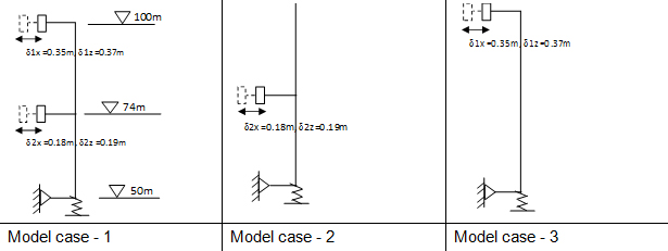
Fig.-2: Schematic structural system of model cases
At stair tower base level, the tower supporting bracket will exert reaction on the existing 2770 deep beam at 4 support locations. For comparison study, support reactions from the stair supporting bracket for Cases 1 to3 are analysed. It is observed that in case 3 the reaction values are much higher in most of the ULS combination. Hence it is not efficient option for the purpose. Further comparison study done between Case 1 & Case 2. To perform the comparison between Case 1 & 2, support reactions at 74m elevation are analysed. It is observed that the horizontal force values at 74m tie location are higher for case-2 as compared to Case-1 in most of the ULS combinations. Thus it is inferred that case-1 is most efficient option.
Design of Tie member End connections
Tie members are mostly axial members which are connected between stair tower column at one end and strong member of BF structure at another end. It helps the stair tower to act as coupled structure. Detailing of the tie member depends on stiffness of the stair tower. At a tie level it may require taking horizontal support along both x & z direction or only along z direction. For only z direction support system, the tie member will have only axial load. To take horizontal support along x direction it will be required to provide horizontal bracing system preferably cross type bracing between tie members. For cross type bracing to reduce the member size tension onlybehaviour can be achieved by providing turnbuckle in bracing members. There is a vertical movement of the existing BF structure due to thermal load. To avoid the additional stress in the tie member due to vertical movement of BF structure, vertical pin connection is provided at both ends of the tie member. These vertical pins allow rotation at tie member end during vertical movement of BF structure.
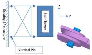
Fig.-3: Vertical pin
Erection Stage Analysis
Due to limitation of erection space availability, erection crane capacity, crane boom length and duration of erection, modular construction is to be adopted. Modular construction concept will reduce erection time and labour cost. The whole stair tower under consideration is divided into six modules as shown in Fig.-4, based on the handling limits received from erection contractor and transporter. Members of each module are assembled at fabrication yard, then the modules are transported to site and all modules are connected through bolt to each other at site by column splicing.
The different erection stages of the structure will not match with the design conditions applied for the in-place analysis of the complete structure. Therefore, it is required to perform construction stage analysis depending upon the sequence as well as various stages of erection. Basic wind speed for the construction stage analysis considered as per section 3.1(5) of EN 1991-1-6:2005. As per code, the basic wind speed value has been considered for erection duration up to 3 months.
For erection, it is required to lift the modules to place at proper location. Lifting plan of the modules to be decided jointly with the erection contractor. Accordingly lifting analysis and design is carried out for each individual module.
From the erection and lifting analysis there is requirement of some additional temporary members which may be removed after completion of erection.
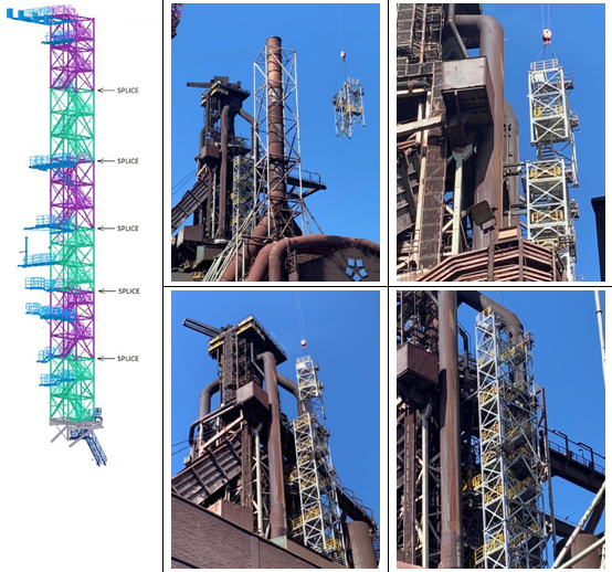
Fig.-4: Erection stage analysis and modular construction
Results from the Parametric Study
Stair tower is a secondary structure and hence deflection of the structure is a more pertinent parameter in design evaluation than member stresses. To achieve deflection control in an economic design, it makes sense to utilize the higher stiffness of the equipment structure which the stair structure services by suitably connecting the two units. This however, brings in an additional complexity of coupled motion of the two units. In this study attempt is made to arrive at a static solution of the problem through deflection compatibility of the two structures. The independent deflection of the equipment structure is applied as load to the stair tower, connected through ties so that under quasi-static wind loads the two units behave in coupled manner of compatible deflections.
By connecting the stair tower with process equipment, the tower structure sway pattern becomes integrated with the equipment sway. Hence it is not required to check the sway limit of stair tower as independent tower after connecting with lateral ties.
Modular construction is increasingly being accepted by most of the construction industries worldwide. In case of Modular construction, it will be required to perform few additional design considerations based on the construction logistics. It may require adding temporary members based on the lifting & transportation analysis of different modules.
Conclusion
From the results of the parametric study it is found that independent stair tower of 50m height resting on flexible base is not feasible and will not meet deflection/ sway criteria. Hence ties at various levels are required and to ensure compatibility of deflection of coupled structure, sway values of BF structure at the various tie levels are obtained from OEM (Original Equipment Manufacturer) and applied as displacement load input to the stair tower model. The tie members are designed for the ensuing axial forces and vertical shear forces and the connections are designed accordingly to transmit the forces at the interface. There will be vertical movement of the process equipment due to thermal load which also being taken care of in the detailing of lateral tie member connection.
© Tata Consulting Engineers Limited. All Rights Reserved | Site Credits:DV


