A Steel Plant undergoing expansion had set up coke oven batteries (COB), namely COB 10 and 11, with wet quenching provision to meet the increased demand of coke. Two new Coke Dry Quenching (CDQ) plants for COB -10 & 11 along with waste heat recovery boilers have also been installed. There are three existing COBs 5,6, and 7 along with respective CDQ plants and a common boiler. Surplus steam from the existing boiler and the steam available from the new boilers at different temperatures and pressures were transported through pipe over a distance of 1.8 km and combined to feed the steam turbine to generate 40 MW power. The assignment is an engineering excellence successfully accomplished by TCE considering the challenges due to (a) variable steam parameters from different sources, (b) Layout of power plant building in a space smaller than usual practice, (c) routing of the steam pipes and DM water pipe through the existing congested layout and (d) construction challenges within limited space.
Hot coke obtained from COB is cooled by quenching in absence of air. Quenching may be wet or dry type. Wet quenching is done by water and dry quenching is done by nitrogen. Nitrogen absorbs heat by cooling the hot coke at the time of quenching and hot nitrogen is fed to the boiler to generate steam. In the process the nitrogen losses heat and the cooled nitrogen is returned to the dry quenching plant to quench the hot coke again. This cycle is repeated continuously for sustained generation of power (Fig 1).
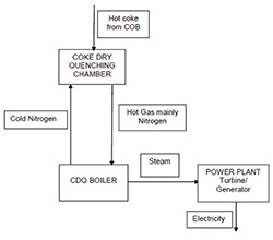
Fig 1
- Tata Steel Limited (TSL) had set up new coke oven batteries (COB), COB 10 and 11 to meet the coke requirement of Jamshedpur steel plant as part of their 9.7 MTPA expansion project and now has installed two Coke Dry Quenching plants, one each for COB-10 & 11.
- Initially wet quenching of hot coke was envisaged. As wet quenching consumes large volume of water and energy inefficient, dry quenching of coke was planned for COB 10 and 11 in addition to wet quenching facilities originally provided.
- Coke Dry Quenching (CDQ) facility includes dry quenching process (CDQ) and a heat recovery Boiler. Each new CDQ boiler has a HP steaming capacity of 60 TPH.
- HP steam generation capacity of existing CDQ 5,6,7 common boiler is around 75 TPH. Even after meeting existing process steam demand, surplus quantity of 25 TPH HP steam is available. As a result, a total (2x60+25) of 145 TPH HP steam can be supplied to CDQ power plant steam turbine, which can generate around 40 MW of power.
Layout is furnished below (Fig 2) for ease of understanding of the engineering challenges during design and construction.
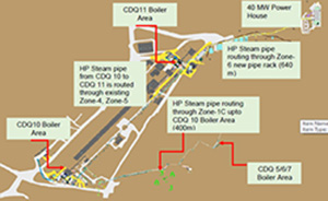
Fig 2
- Engineering challenges and mitigations are described below;
- a) Challenge
- The power plant site is approximately 640 m away from CDQ 11 Boiler, 1500 m away from CDQ 10 Boiler and the distance between CDQ 5,6,7 Boiler and power plant is around 1.8 km. All the three steam sources are located at different locations. HP steam from three steam sources with different parameters have been mixed and supplied to power plant through 1.8 km HP steam piping for power generation (Fig 2). Engineering for conveying of steam from various sources and having different parameters for such a long distance and achieving desired parameters at power plant turbine inlet is a critical and complex phenomenon.
- Mitigation
- Multiple Pressure Reducing Valves (PRV) located at the outlet steam pipe of boilers were introduced and a cascade close control loop has been introduced to ensure proper pressure and balancing at piping nodes. Thus proper steam mixing from different boilers is done facilitating the relatively low pressure steam from CDQ 5/6/7 boiler to flow in the steam network for all possible load combinations of CDQ10, CDQ11, CDQ 5/6/7 and STG. Steam dynamic study for the complete network has been done to validate the concept. The design of cascade control loop for control valves and introduction of pressure reduction valves are unique features for sustained trouble free operation of the power plant.
- b) Challenge
- Installation of the power plant along with the auxiliaries like Cooling Tower, Transformer Yard, CW Pumps & CW Chemical dosing system, Pipe rack, Office building and Electrical Building had to be accommodated within the limited area that was available after demolishing the existing structures. This is a layout challenge.
- Mitigation
- Induced draft cooling tower with above ground basin and horizontal CW pumps eliminated the need of Forebay system enabling reduction of space and accommodating the cooling system within the available limited space. Further, standby cell in the cooling tower has been eliminated to reduce the space requirement. All three cooling tower cells are working during normal plant operation. VVVF drive based power supply for cooling tower fan motors has been adopted for energy saving round the year. A composite power house cum office building cum electrical building has been designed to suit the space availability.
- c) Challenge
- Make up DM water pipe from existing facility to 40 MW power plant (900 m) has been routed through congested area. HP steam pipe has been routed from CDQ 5,6,7 area up to CDQ 10 area (400 m) through heavily congested facilities (Fig 7).
- Mitigation
- Existing pipe bridges/ building/ facilities have been used to the maximum possible extent (Fig 6) and the rest portion by new supports (Fig 7). Adequacy of existing facilities wherever used have been ensured by forensic engineering. New supports have been avoided to the maximum extent to reduce possibility of fouling of the new foundations with the existing one & underground installations. Prefabricated structures have been erected, where space for new supports were not available (Fig 8).
- d) Challenge
- The power plant has been built up in an area which was full of existing structures, over ground and underground installations. All existing facilities were demolished for power plant construction. Demolishing of structures within limited space maintaining safety and material movement within confined space during power plant erection are the major construction challenges.
- Mitigation
- Concrete structures constituted major part of dismantling. Brick tunnel along with structural steel racks/ trestles were also dismantled. Conventional methods of dismantling by deployment of skilled workforce was planned for simple and safe execution. Sequence of dismantling was thoroughly planned for smooth execution of the work in limited space in a safe and secured manner.
- 3D Modelling of the project
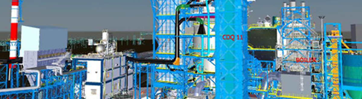
- All detailed engineering except enabling work was done on 3D Platforms (Revit, Plant 3D, Navisworks, PDMS) - Fig 9 & Fig 10. The walkthrough model was also generated. This ensured a complete 3D engineering where piping, equipment, structures etc were integrated by TCE and all corrective actions based on clash checking were possible.
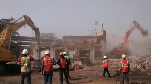
Fig 3 Dismantling work in Power Plant area
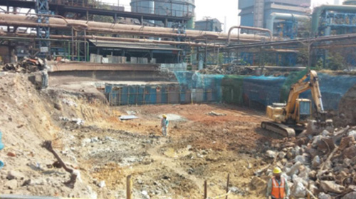
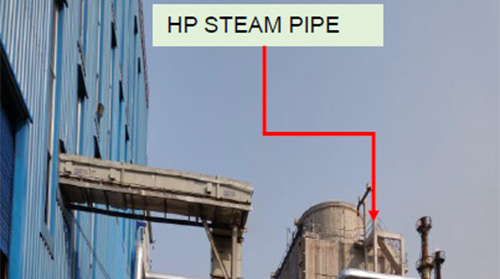
Fig 5 Steam Pipe and rack to Power Plant
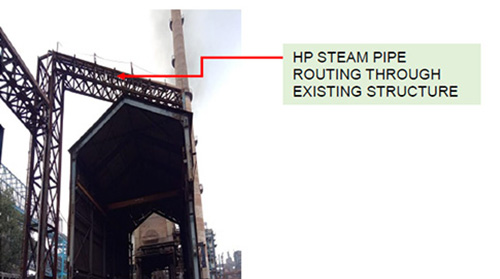
Fig 6 HP Steam pipe
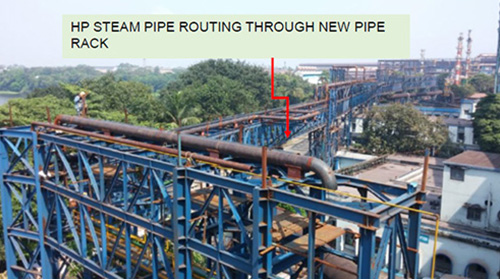
Fig 7 Pipe routing through congested area
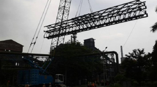
Fig 8 Prefabricated modules of Pipe rack to overcome space constraint
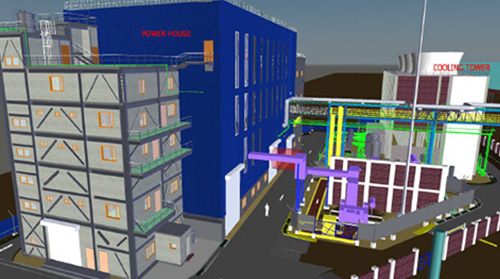
Fig 9 3D Model – Power Plant and Cooling Tower
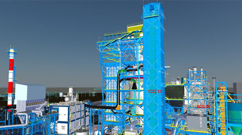
Fig 10 3D Model – CDQ 11 and Boiler 11
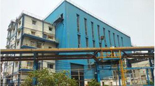
Fig 11 Power House building
AUTHORS
Prosenjit Chatterjee
Manager, Vicky Vivek – Sr. Manager
Asish Saha
General Manager
Sanjoy Chowdhury
Sr. General Manager