

TCE is taking great strides towards adopting digital engineering tools for achieving speed, accuracy and predictability in engineering design for projects with an aim to adopt Industry 4.0 standards. Use of 3D design tools for complete engineering design has become the way of life for engineers at TCE. This article aims to present a case study where 3D engineering tools were used extensively for multidisciplinary engineering work for an industrial project in brownfield conditions covering the entire phase for collection of data for existing plant to completely integrating the existing data with the proposed plant extension and required enabling work for creation of the space for the expansion in the existing plant. The harmonized multi-disciplinary work approach resulted in an integrated project model incorporating all designed features required for the plant to produce highly accurate estimate of the work and predictable outcome.
Introduction
As the engineering industry moves towards adopting the standards of Industry 4.0, the use of digital simulation tools are being used to create realistic, scaled and engineered design solutions to produce accurate virtual models. The engineers at TCE are using advanced digital tools in all sectors of engineering. Engineering projects are simulated and visualised digitally by creating a ‘digital double’ of the project before construction. Digital simulation brings a lot of predictability to engineering project management. Project delays are avoided and cost is managed well with the use of digital engineering systems. Modernisation and upgrades of old plants are also easily managed with digitisation so that there is minimum disruption.
One overseas steel manufacturer required to extend its product portfolio to more advanced products by increasing capabilities and improving quality. This required capability and quality requirements of its Hot Strip Mill (HSM) Reheating Furnaces to be enhanced by installing two new walking beam type furnaces (WBF). One furnace would be installed in area created by demolition of an existing older pusher type furnace (PTF) and the other would be installed by extension of the furnace building. TCE was entrusted with the engineering work for developing project design details to enable an accurate estimate (±10%) of the construction works to be prepared for the final detailed stage of engineering.
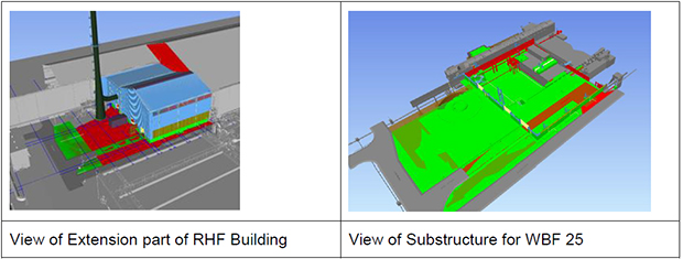
The existing plant building housing the furnaces comprises three bay structure termed PE Hall, PB Hall and PD Hall. To enable space for one of the new furnaces, the existing PB & PD hall requires an extension by 45.1 m towards west of existing frame structure at gable end grid 32A of PB Hall. The existing gable end near grid 32A will be dismantled and new gable end will be erected along grid 30. The existing column at grid 31 needs to be dismantled to accommodate new furnace. The existing roof system of PE hall would be supported by existing roof girder along grid DE due to removal of column 31. The project work components are listed as below:
1. Extension of existing PB Hall and PD Hall. 2. Removal of existing column along grid DE in line 31. 3. Modification of existing Semi-portal crane supporting structure. 4. Combined E room and Hydraulic room of WBF- 25. 5. Dismantling of Crane & Surge girder of PE Hall. 6. Dismantling of Semi-portal crane supporting structure. 7. Dismantling of South side wall of PE Hall. 8. Dismantling of existing Gable end of PB & PD Hall.
Scope of the 3D Engineering Work
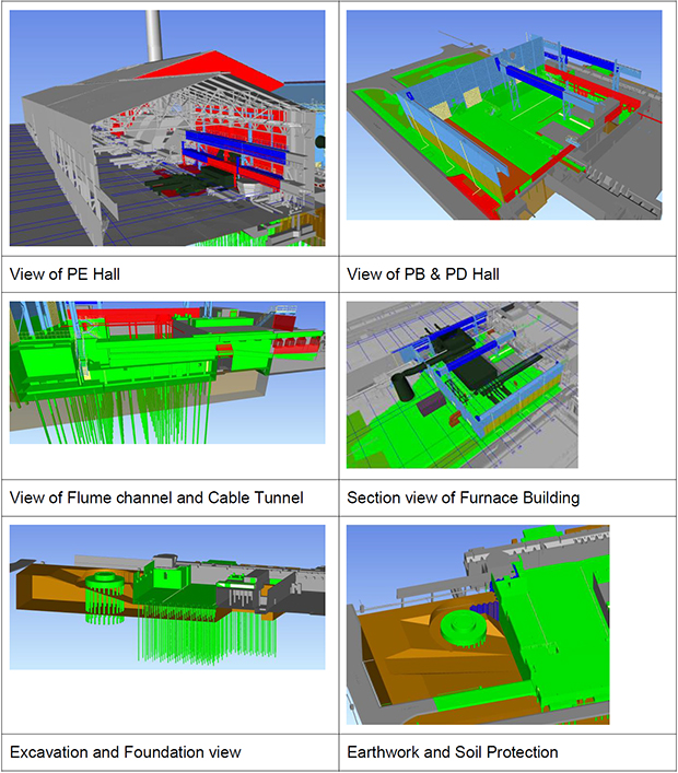
The engineering for above modification involves the following steps: Preparation of scheme drawings based on approved OSR & discussion with client. Preparation of demolition drawings in 2-D platform & colouring the 3-D model of the existing structure Structural analysis & design Importing data from 3D Laser scan Preparation of 3D model for - Civil & Structural - Piping & Electrical - Mechanical Integration of civil & structural model with scan model Integration all the models
Development of the 3D Model of Structure
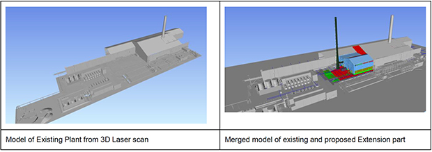
One of the main objectives for the project was to integrate the model for the new structure in extension part of building with the laser scan image of the existing part. This model of the existing structure was a non-intelligent model since no design related data could be extracted from the model. Only the existing geometry was available to be integrated with the model to be developed for the extension part of the structure. Many challenges were posed to the design team in collating the scan data and reconciling it with the “As-Built” information available from 2D drawings. The scan data in raw point-cloud form had to be processed and formatted through various software tools to make it ready for import into 3D model. Particular problem was encountered in fixing the baseline of the scan model with that of the design model since the coordinates (X-Y-Z) of the scan camera point had to be exactly matched to the plant grid coordinate system to ensure proper fitment between existing and new structure.
© Tata Consulting Engineers Limited. All Rights Reserved | Site Credits:DV


