
PLANT CONTROLS
Unit master Control (UMC) for Combined cycle power plants provides flexibility to the operator to control GTG’s ( Gas turbine Generator) , STG’s ( Steam turbine generator ) and HRSG’s ( Heat Recovery Steam generator ) depending upon the physical condition of these Equipment’s and demand.
In this article, we will cover the brief notes on the Unit Master Control (UMC) for combined cycle power plants with multiple GTGs and STGs, which is one of the important controls for the CCPPs.
The DCS in the CCPP provides various controls for safe and effective control and monitoring of the various units and auxiliaries. The supervisory controls include the UMC. The other synonyms are Plant load/master control, Coordinated Master Control (CMC), Automatic Power Regulation (APR), Automatic Generation Control (AGC).
The main aim of UMC is to equally distribute the MW set points obtained from Load Dispatch Center (LDC) for the running units based on the individual unit capabilities. Apart from this it adjusts the set point during abnormal condition while maintaining the stress level of the GTGs and STGs within the limits. Figure -1
The UMC scheme varies with different factors like type of Gas and Steam turbines and their suppliers, configuration of the plant and their auxiliaries, level of automation considered, etc. And finally, the signal exchanges between the Turbine control system and UMC.
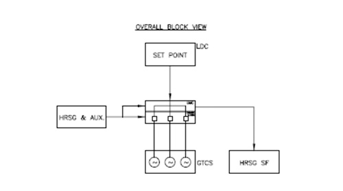
Figure 1
GTCS – Gas Turbine control system
HRSG SF – Heat recovery generator supplementary firing
The arrived set point from the LDC will undergo various plant High/Low selection, Rate control, etc. While arriving at the final set point, it shall take care of the plant auxiliary power consumption. The UMC mode is selected to auto mode only when the communication with LDC is healthy, GTGs are under stable load with remote set point enabled. When all the above conditions are met, the set point is further distributed amongst the participating GTG units equally or through ratio control based on current load and its capability. While STG in valve wide open condition will follow the GTGs . Figure -2
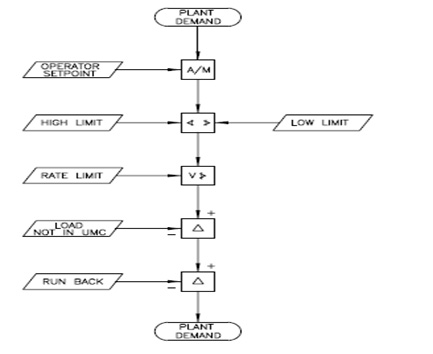
Figure 2
The capability of GTG is arrived based on various factors like ambient temperature, running status of the auxiliaries like wet compression or evaporative cooling operations, primary frequency, etc. The capability of STG is arrived based GTG load and Circulating water requirement.
LOAD CONTROLS
The unit GTG load control set point will undergo high/low limitations with Rate control, deduction of runback load, HRSG impacts, etc. Figure -3. This forms the set point for the GTG load controller.
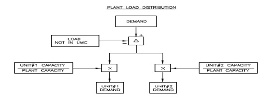
Figure 3
Supplementary Firing (SF) is required to supplement the load requirement and export steam requirement [for water plant (Desalination plant) or other purposes]. Accordingly, the set point is arrived. During low and high-water demand of Desalination plant , the Supplementary Firing will meet the steam requirement and vice versa.
The SF load also distributed to participating units based on the individual unit SF capability through ratio control. The SF capability depends on the GTG load and no of burners in operation. Figure-4. This forms the set point for the fuel flow control.
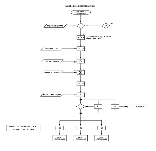
Figure 4
RUN BACK MODE
During abnormal conditions like Steam turbine trip or abnormal steam parameters, the healthy units shall be taken to stable load conditions, without tripping the entire plant. This is achieved by reducing the loads of heathy units by means of the Run back phenomenon. This involves various calculations to arrive at the optimum stable load of running units. When the units are equipped with supplementary (Oil/ Gas) firing in addition to Heat recovery, it is the supplementary load which is reduced first. Say if the ST trips the equivalent load of supplementary firing is calculated based on the steam flow or based on the power output. Which is then converted to equivalent thermal load for further processing. Figure 5.
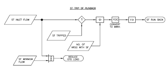
Figure 5
Like all other runback conditions, the condenser runback also calculated dynamically based on the various measurements available. This runback ensures condenser vacuum under abnormal conditions. The heat input to condenser from various sources like steam turbine exhaust, steam bypass, etc. is calculated and comparted with heat carry over by cooling water. The heat carryover capacity depends on the no of Circulating water Pump’s in service. This shall be arrived from circulating water flow measurement. The excess heat is reduced first by reducing the supplementary firing. If heat reduction is still not enough, the balance heat input reduction is done by GTG load reduction. Figure 6
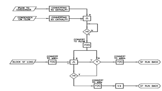
Figure 6
Also, if the plant is integrated water and Power plant, the calculation methodology will have impact based on the water grid demand. IF the water demand is priority, then the water plant can continue running with run back while compromising on the efficiency of the plant. However, if the water plant trips, then also the run back is initiated.
Thus, the above one is a brief concept of the Unit Master Control implemented in Combined Cycle Power plant.
© Tata Consulting Engineers Limited. All Rights Reserved | Site Credits:DV


