
Wireless Solutions for Power Plants

In a typical power plant, various instruments are used for measurement and control. The traditional method of connecting the signals to the central control room is by wiring (using cables) from instruments to the control room. Wired control networks use communications like 4-20 mA, Hart, Foundation field bus, Profibus, etc.
Wireless solutions are beneficial over wired solutions for the following advantages:
Advantages of Wireless:
- Complete instrumentation & control cables requirement of field instruments is nullified giving cost-benefit towards supply & laying of cable, cable trays & accessories.
- Measurement of parameters at remote places & in inaccessible locations to cable trays is possible using wireless solutions.
- Expandability/scalability is more flexible in wireless than in wired solutions.
- Saving in operational cost.
- Ease of adding extra measurements to cater to advanced process controls & optimization packages, asset management, diagnostics & predictive maintenance.
- Very useful to deploy wireless solutions in extreme environmental conditions for wired installations (hot, wet, corrosive, etc.)
- Ease of maintenance
- Ease of installation
- Reduction in time of installation & commissioning
Wireless technology shall be used for the following measurements:
Pressure, Temperature, Vibration, Level, Flow, pH, Conductivity, Gas leak detection, Partial Discharge monitoring, Lux, Current, Voltage, Humidity, Wind speed, Free Chlorine, Discrete inputs, Discrete outputs, Flame Detection, etc.
Wireless Configurations:
There are different types of wireless configurations available to connect any instrument to a wireless network. This writeup focuses mainly on those different types of connectivity to make any instrument connected to a wireless network. Different wireless configurations for different types of instruments are summarized as below:
Type 1: Wireless configuration with ISA / WI HART protocols
This type is for instruments with direct wireless output. The transmitter output is available as a wireless signal. Two types of wireless protocols are available. They are
ISA 100.11a protocol
Wireless HART (Approved standard IEC – 62591)
- Suppliers for transmitters with ISA protocol output – e.g. Yokogawa
Suppliers for transmitters with WiHart protocol – e.g. Emerson, ABB
- Typical circumferential distance covered by the repeater to receive wireless signal – 100 m radius surrounding the repeater without a line of sight between transmitter & repeater.
- Repeater & ISA gateways have antennas & they need to have a line of sight and communicate to a maximum distance of 600 m to 1 km.
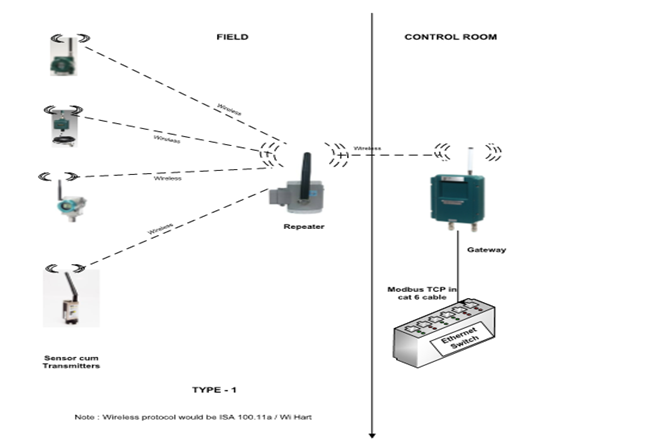
- No. of transmitter signals that can get connected to a gateway – 20 to 100 signals.
- Gateway antennas are provided on top of the control room & cable runs between the antenna and the gateway in the control room.
- ISA gateways transmit the signals of all transmitters to the plant control system (DCS) via Modbus TCP, which can get connected to the Ethernet switch of the plant DCS system.
- Following are the parameters that can be measured with such wireless instruments: Pressure, Temperature, Vibration
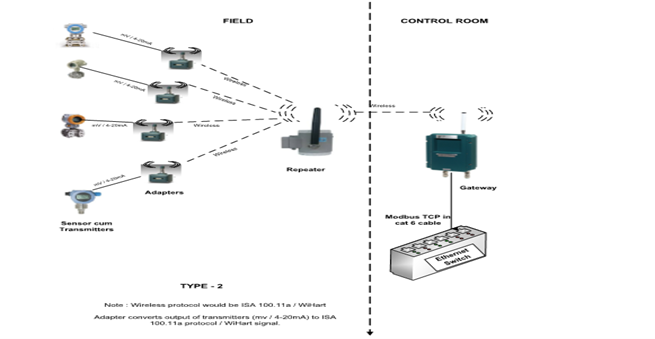
Type 2: Conventional transmitters converted to wireless (ISA / WiHart) protocol with adapters.
This type of configuration is used for instruments that do not have direct wireless output. Any instrument having mv / 4-20mA output shall be converted to wireless. Parameters measured – Level, flow, Lux, etc
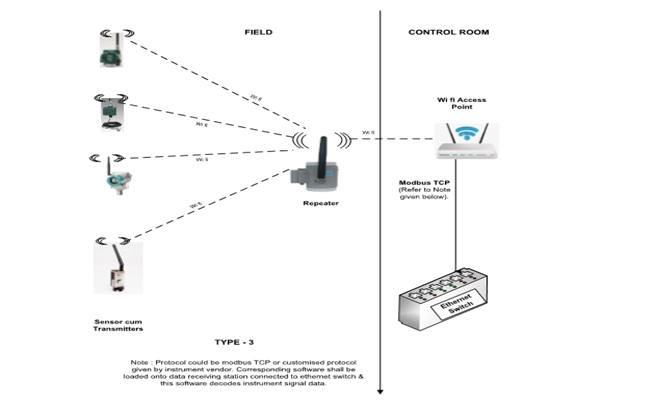
Type 3: Sensor with wifi output (IIOT sensors)
This type is applicable for instruments with direct wifi output. Parameters measured: Vibration, temperature, humidity, etc.
Type 4: Conventional transmitters converted to give Wifi output with converters.
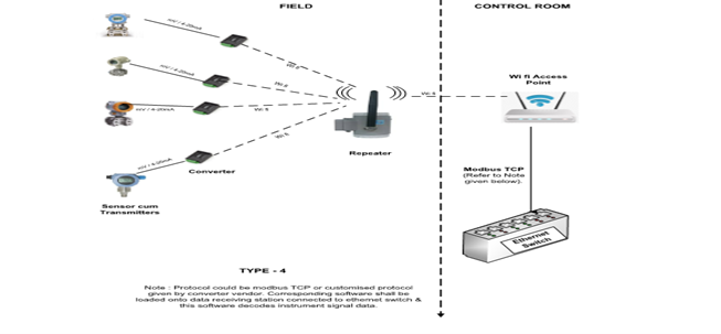
This type of configuration is used for instruments that do not have direct wireless output. Any instrument having mv / 4-20mA output shall be converted to have wifi output.
Type 5: Conventional instrument with Modbus output connected to Wifi network with converters
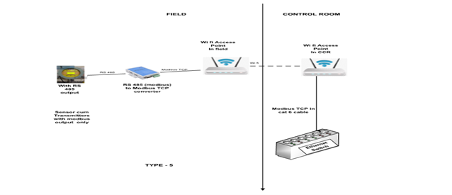
This shall be used for the instrument with Modbus output. Parameters measured – Partial discharge, Lux, Hydrogen leak detection, etc
Type 6: Wireless instruments used in IIOT application
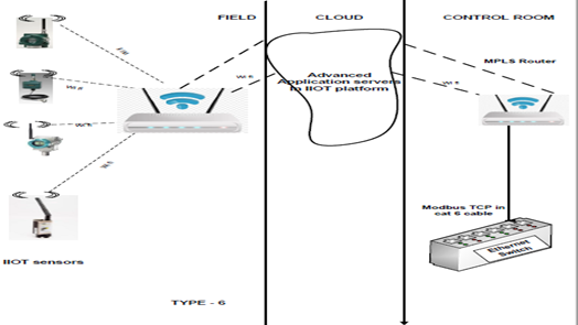
This configuration depicts the usage of the IIOT application in remote cloud servers.
Typical configuration of wireless transmitters from various areas of the plant to CCR–option 1
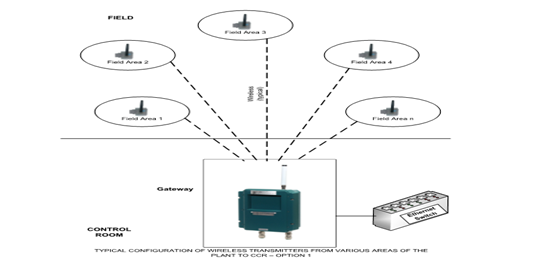
- Wireless transmitters in different areas are grouped based on geographical location.
- of Repeaters are considered in each area according to the no. of signals in that area.
- Repeaters are positioned in such a way to have a direct line of sight with an antenna if Gateway in CCR.
- Multiple repeaters in the plant communicate to the ISA gateways.
- This is the most optimal way of connecting all wireless transmitters to the control room.
Typical configuration of wireless transmitters from various areas of the plant to CCR–option 2
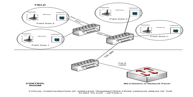
- This will increase response time but involves FOC cabling throughout the plant.
- Redundant configuration is also possible by duplicating adapter/converters/repeaters/gateways.
- Limitations of wireless solutions:
- Response time would vary from 1 second to minutes & hence not recommended for control applications.
- This is highly recommended for measurements of the following applications:
- Monitoring measurements
- Efficiency calculations
- Ad-hoc measurements
- Equipment health monitoring like vibration, oil pressure, corrosion, airflow, etc.
- Health & safety systems – Gas detectors, analyzers, etc.
- Environmental measurements – pH, Cl2, Wind speed, Lux, etc.
Wireless technology is susceptible for the following
- Attenuation
- Distortion
Interference
- Propagation
However, these failures can be detected & alarmed.


