
Seismic Margin Assessment (SMA) of Safety Critical Piping in Nuclear Power Plants of India.
The SMA method has typically been used in other countries for the safety evaluation under seismic conditions of existing nuclear facilities. It considers seismic intensity level which is beyond design basis earthquake events, also referred to as RLEs (Review Level Earthquakes). Regulatory authorities in India have also demanded SMA evaluations for the existing nuclear facilities to ascertain safety in the event of earthquakes.
There are two seismic margin assessment methodologies, developed by
1. EPRI (Electric Power Research Institute) – known as deterministic SMA and
2. US NRC.- known as PRA-based SMA.
They are different in systems modeling and capacity evaluations. Capacity calculations of systems and components are calculated as High Confidence of Low Probability of Failure (HCLPF) values in deterministic SMA. In PRA-based SMA, capacity evaluations of SSCs are calculated by probabilistically defined fragility functions.
The deterministic SMA approach relies on conservative assumptions to simplify the analysis as stated below. (Note, in the event components that cannot be screened out using these conservative assumptions, the assumptions are reviewed and the conservatism is relaxed.)
- The seismic demand is calculated by an elastic seismic response analysis using an elastic response spectrum. This means that the vertical and horizontal components are seen to behave linearly and can be scaled linearly to the RLE. As shown above, this is conservative due to the presence of aseismic bearings and this assumption may be relaxed if components are not screened out.
- Seismic demand on equipment supports may be determined from original design calculations or by calculating new seismic demand loads using the equivalent linear static seismic approach.
- The seismic demand calculations are based on a static analysis where dynamic forces are calculated as equivalent maximum static load. This allows for the simple load combinations according to the following:
1. Only primary stresses are considered for SMA at service level D conditions for pressure boundaries (ASME BPVC Section III). Secondary stresses such as restraint of thermal expansion and support displacements are not included in load combinations due to the relatively low number of seismically induced cycles does not result in failure (IAEA, 1993).
2. The demand is combined with normal operating conditions (NOL) and SSE conditions, which are expected to occur concurrently using load factors of unity.
3. Since SMA is based on a linear analysis, load combinations may be expressed in terms of ‘stresses’, ‘forces’, ‘moments’, ‘displacements’ or any similar relevant concept.
4. To account for beyond elastic behaviour, as this is desirable during a SSE (as it acts as the main damping mechanism), an inelastic energy absorption factor is considered. This inelastic energy absorption factor is function of strain ductility, i.e. the ratio of permissible inelastic to yield deformation and is associated with a permissible level of inelastic distortions specified at a failure probability of about 5%.
- The lowest natural frequency of the components is checked. If the natural frequency of the component is more than 33Hz, then the equipment is considered “rigid” and the ZPGA is used in the demand calculations. If the natural frequency is known, the maximum acceleration from the response spectrum for the frequency range (from natural frequency to 33 Hz) can be used instead of the peak. If the natural frequency is estimated (but not known) to be below 33 Hz (this is generally true for piping), the equipment should be considered “flexible” and the peak of the response spectrum should be used as a conservative estimate of the demand.
- No failure due to fatigue is considered due to the relatively low number of seismically induced cycles. The margin in low cycle fatigue failure is incorporated into the ductility factor.
- For piping that is schedule 40 or higher, (which is normally the case for nuclear safety related piping) pipe buckling will not be considered when subjected to earthquake loading. For supports, the buckling capacity is determined using ASME design acceptance criteria (i.e., ASME B&PV Code Section III, Subsection NF-3322).
- Component is assumed as undamaged having no significant erosion or corrosion.
Calculation Of Seismic Margin
The factor of safety is calculated as the ratio of seismic capacity to seismic demand (Ds). It is sufficient to analyze the system once for normal operating loads and earthquake loads using the review level earthquake and then extrapolating the results to obtain the HCLPF value of earthquake in terms of PGA. The HCLPF value of PGA is obtained by increasing the review level earthquake (i.e. SSE) PGA by a factor which is ratio of remaining capacity to seismic demand and then multiplied by ductility factor.
In a typical assignment, as built data/drawings needed to be studied for 19 safety related piping and supports involving 130 models. This was a challenge since enormous as built design and site details had to referred (2500 drawings) for Safety related Class 1, Class 2 & 3 piping. The job was executed with utmost care and perfection. Rigorous modeling in piping stress software and client review was involved.
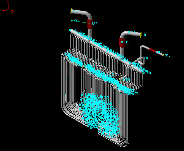
TCE performed Seismic Margin Assessment of Primary Heat Transport system –Class I system for a typical assignment
TCE has more than 40 years of experience in working with prestigious nuclear projects and regulatory authorities, having been a part of many nuclear projects in the nation. This has developed us with deeper understanding of the complexities, concepts with unique competence in handling challenging assignments.


