
Restoration of 95 Years Old Bar Yard Building
The Bar Yard building is a structural steel framework with crane girders and was constructed during 1925 – 1935. The health of the foundation and superstructure was observed to be in poor condition. Detail inspection revealed significant corrosion, misalignment of column & crane, damage & twisting of certain structural elements, deterioration of health of the foundation. Column foundations were either plain lime concrete or plain cement concrete. Thus the dilapidated condition of both superstructure and substructure rendered the building unsafe and unserviceable.The challenging task of making the building structurally safe and serviceable under the Plant running condition was successfully engineered by TCE and the structure was restored to be safe for the operation of increased crane load from 8 MT to 25 MT.
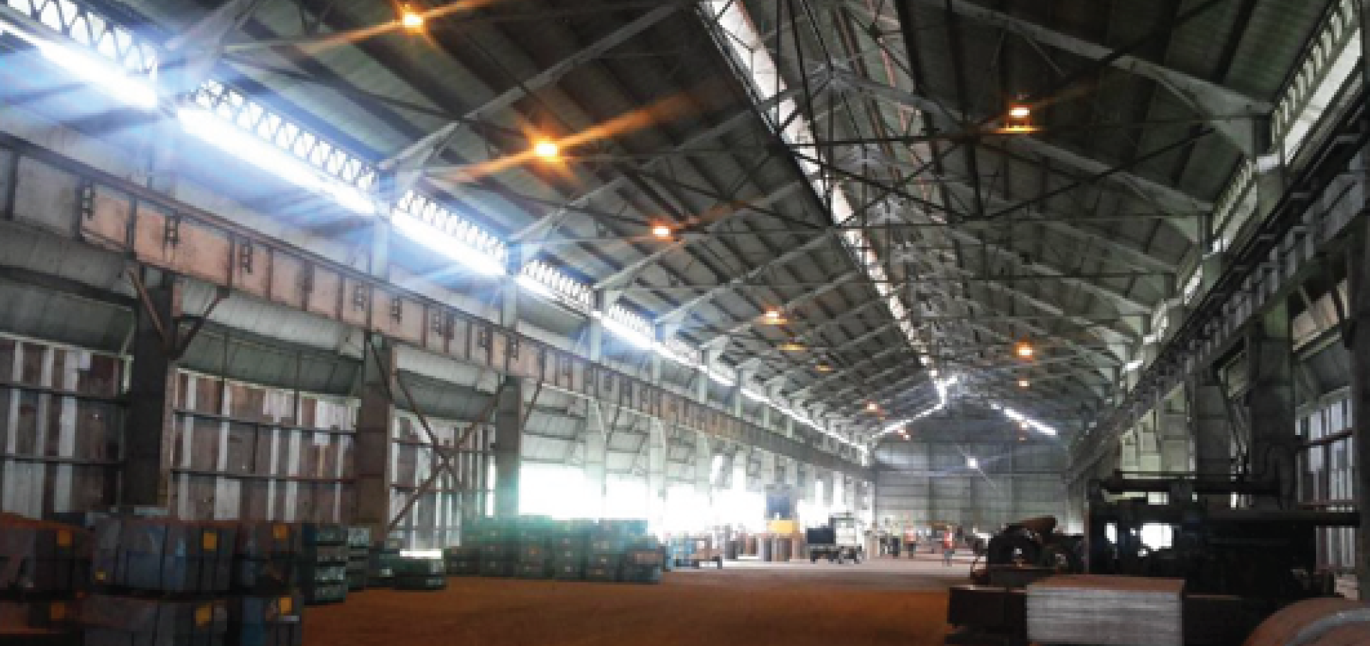
The Bar Yard Building is used for processing baby coils, material storage and material handling. The plan dimensions of the building are approx. 160m x 25m and the height is approx. 16.0 m.
Initially 1 no. 25 MT & 1 no. 15 MT capacity EOT cranes were under operation for handling the material. Later, 25 MT crane was dismantled due to vibration in the building and the other 15 MT crane had been operated with reduced capacity of 10 MT which was further de-rated to 8 MT.
The Owner desired to bring the building back to safe & serviceable condition with enhanced crane capacity of 25 MT.
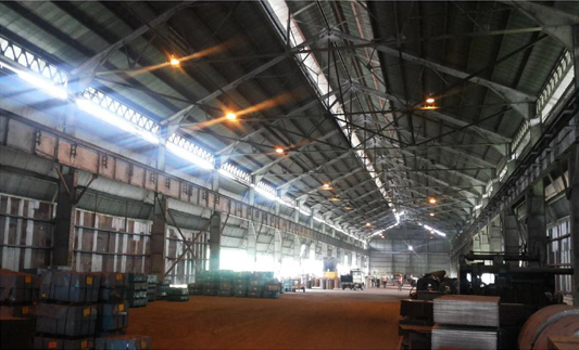
Fig. 1 Bar Yard Building
Some of the engineering challenges of strengthening of Bar Yard Building are described below:
• Restoration of the building without any shut down.
• Most of the columns were distorted and non-aligned from the centre line leading to additional sway and bending moment during crane movement.
• The web/flange plate of columns, bracings, gussets, rib plates were pitted and rusted at many places thus reducing the cross-sectional area of the structural members and increasing the stress.
• Most of the rivets were loosened and pitted resulting inadequate capacity of the connections.
• The horizontal and diagonal distances of the crane girder and rails were found beyond tolerance limit. Centre to centre distance and the top level of the rail were also found to be not uniform. This caused eccentric movement of the crane inducing torsional stresses to the crane girder and vibration to the structure.
• Permanent sagging of crane girder was visible.
• Survey & measurement at site revealed that centre to centre distances between two rows of columns over the length of the building varied as high as 475 mm turning the building footprint skewed and inducing undesirable torsional stresses and increased shear and bending stresses in the main load bearing structural elements and foundation.
• Results of Hammer and UPV tests revealed deterioration of concrete in the foundations. Spalling and cracks were observed.
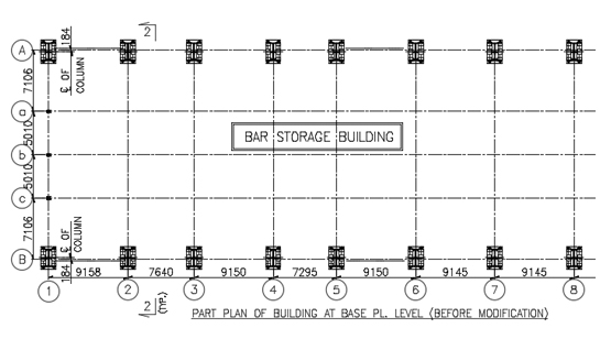
Fig. 2 Part Plan of the Building (before modification)
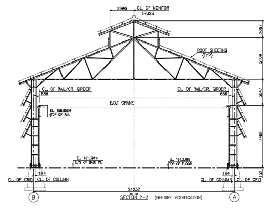
Fig. 3 Cross section of Building (before modification)
From the nature of distresses described above and due to the age of the building, strengthening of the building holistically instead of individual members was felt to be a solution. Therefore, it was necessary to have an innovative approach which would relieve the main structural members off some of the load. As such, external inclined (raker) columns were provided both transversely and longitudinally(Fig. 5,10 & 11).This established an alternative path of flow of the horizontal load from crane surge and wind directly to the raker columns allowing the main vertical columns to carry only the vertical load. This provided enough margins to take care of reduced cross sectional area of the columns (due to corrosion) and additional moment due to off-centering of the alignment. Since, the main columns got rid of the horizontal forces, moment and shear to the existing foundations got reduced imparting stability and safety. Raker columns also provided stability against the torsional force on account of the skewness of the building.
The crane girders were replaced with new ones as the fatigue life of the same had surpassed and few were found to be sagged.
The roof truss and the roof legs of the columns were less corroded and the same were checked for design adequacy with the stipulations of the then current wind loading code IS:
875 (Part 3) – 1987 (reaffirmed 1997). Few members in the roof truss were observed to be failed (Fig. 6) and same were strengthened by additional plates as per the requirement.
Restoration work started with construction of Raker column foundation and erection of Raker columns. Erection of Raker column and replacement of crane girders were planned zone wise in such a sequence so that the bays undergoing restoration did not interfere with the bays under Plant operation. The planned activities in a sequence enabled the restoration without any Plant shut down.
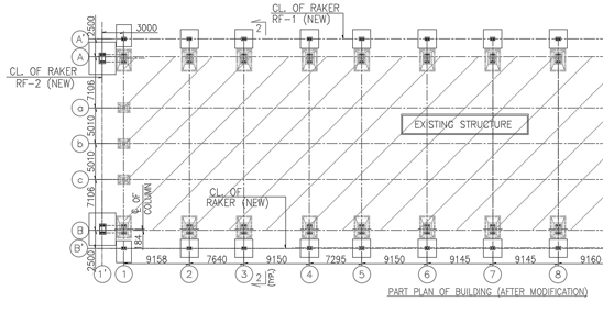
Fig. 4 Part Plan of the Building (after modification)
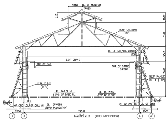
Fig. 5 Cross section of Building (after modification)
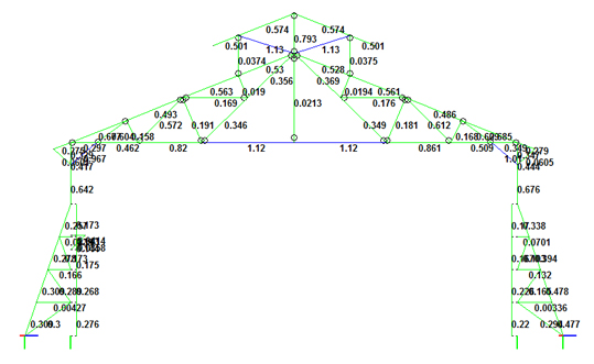
Fig. 6 Failed members (BLUE HIGHLIGHTED) due to wind as per current Code
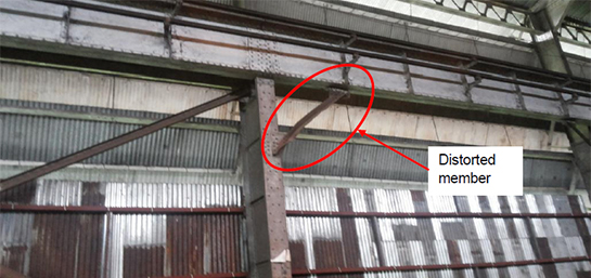
Fig. 7 Elevation of Bar yard Building (Before modification)
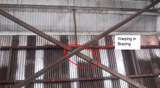
Fig. 8 Elevation of Bar yard Building (Before modification)
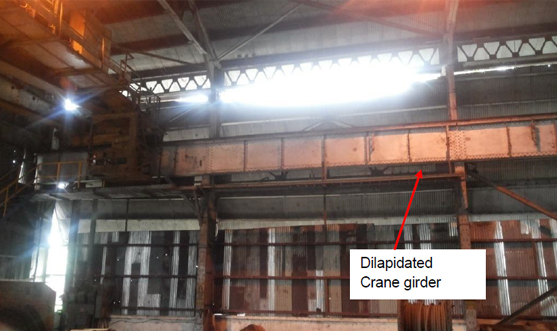
Fig. 9 Part elevation – Crane bay
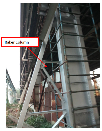
Fig. 10 Raker Column
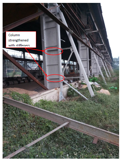
Fig. 11 Raker Column and Column strengthening


