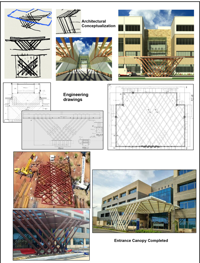
Engineering of Entrance Glass Canopy
Introduction
TCE has provided “Concept to Commissioning”, including detail engineering services of all disciplines to one of the most prestigious hospital projects. TCE has designed and erected three structural canopies for this Hospital and the largest one spanning 20m x 15m in plan (Ref Fig-1).
There were many challenges faced in the detailed design of this canopy, mainly overall serviceability and stability of canopy including glass covering over it, Skewed structural columns to support the canopy on one side, maintaining overall aesthetics and Architectural Design intent, providing effective storm water drainage, managing dimensional irregularities, lifting and erection of the canopy as a single structure on top of the RC columns (5 Nos.) those were already constructed. TCE team were able to overcome all these challenges and successfully complete this grand entrance canopy within scheduled time.
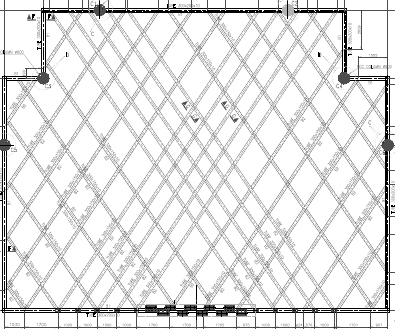
Fig-1 –Plan of the Canopy Structure
Analysis & Design of Canopy
The canopy was analysed and designed as space frame. More than the strength, the serviceability criteria was more critical due to glass covering over the canopy. The actual deflection of canopy was calculated and ensured within permissible limits of deflection as per the provisions of IS: 800-2007. A camber of 25mm was also provided to steel members in addition, as the span of primary beams was 17m.
Since the canopy is covered with glass, it was necessary to ensure the structural deflection does not have any adverse impact on the integrity of glass panel at every support locations during the service life. Also, it was critically checked for required slope post erection of finished canopy. The required slope to avoid water logging, along with the actual deflection values of structural canopy were provided to glass manufacturer to ensure that glass panel design is not affected due to the deflection of canopy structure. Accordingly, glass manufacturer further studied glass panel sizes, fixing details, connection between the two panels and customised glass panel thickness and sizes. Aluminium clips of varying depths (higher depth at centre of canopy) were provided to support the glass panel so as to drain off the rain water.
The skew columns (Ref Fig-2) were provided in two sets i.e. 5 columns in each set. All the columns in one set are connected to the column in other set for achieving the combined action.
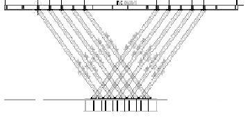
Ref Fig-2 – Skewed Columns (Front Elevation)
The structural beams were connected to the concrete column using circular profiled plates with “Through Bolting”. The connections were designed for combined action of moment and shear.
Canopy Details
Area of the canopy : 20m x 15m
Height of the Canopy : 4m
Main beam size : RHS 200x300x10 (Hollow Sections)
Secondary beam size : RHS 150x300x10 (Hollow Sections)
Concrete column size : 600 mm dia.
Type of Roof Covering : 13.52mm thick SGG PLANILUX glass
Transportation and Erection
Since the entire canopy plan was fabricated in fabrication workshop set up at site, it was necessary that it is transported to location as a single piece. The erection contractor had submitted the lifting and erection scheme which was reviewed by TCE’s execution team from the safety and stability point of view. Moreover, the obstructions coming in the path were cleared so that the transportation would be smooth. Two cranes of 40 MT capacities each, were deployed in tandem to transport the canopy structure from fabrication shop and erect at its desired location.
For additional stability, temporary supports were provided to canopy during erection. After the canopy was secured to RC columns, skewed steel columns were erected and aligned. The temporary supports were removed once the skew column were
erected thereby transferring the entire load on RC columns and skewed columns. The entire operation was planned and executed meticulously with utmost safety precautions.
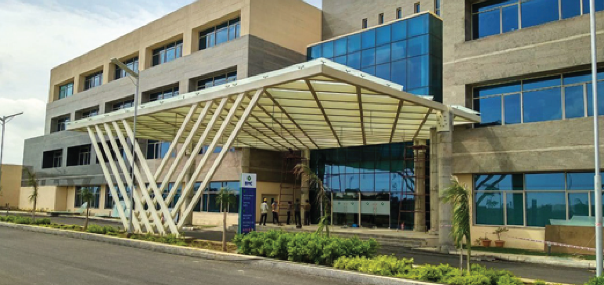
The glass covering was erected later, after carrying out required surface preparation of the canopy members. The entire erection of canopy including alignment took two days with deployment of utmost safety measures at site (Ref Fig-3).
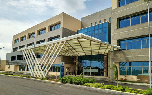
Fig-3: Canopy at the Entrance
These Canopies “Stands out” as one of the key engineering achievements as per Architectural design intent of TCE in this Hospital project, providing our Engineering team the confidence and agility to design many more such Engineering Marvels.
Fig-4: Making of Entrance canopy