Analysis of Control System Architecture

The best design of the control system architecture for a plant is the one where the failure of any component/subsystem does not affect the plant safety. Here, we will discuss the control system of a plant having a truly distributed architecture, handling a total of about 35000 I/O’s covering approximately 15 process blocks.
Quality Control tools such as FMEA (Failure Mode and Effect Analysis) and FTA (Fault Tree Analysis) shall be used to examine the potential failure within a system and its effect on plant safety. FMEA is a bottom up approach, starting at the component level to identify their failure modes and their effects on the subsystems which are on a higher level. FTA is a top down approach, used to identify the failure of the subsystems and the method for determining the causes of the failure.
Both FMEA and FTA can be used to identify the causes of the failure and consequently can be used for the safety analysis of the system and plant.
SYSTEM DESCRIPTION
The Main processor for each process block is located in Main Control Room and redundant processor is located in the Secondary Control Room housed in the respective process block. Hence there is a physical separation of the processors ensuring higher availability.
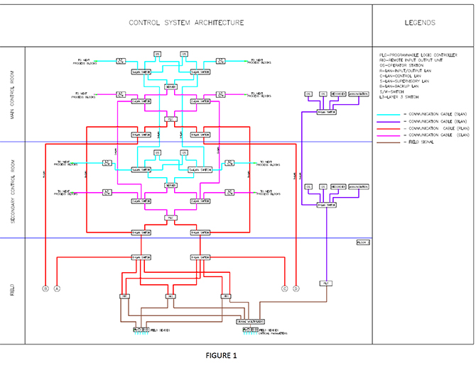
The control system architecture as depicted in Figure 1 is a PLC based control system with three tier architecture in dual redundant configuration namely Input / Output (I/O) LAN, Control LAN and Supervisory LAN referred to as R-LAN, C-LAN and S-LAN respectively. The three network LAN’s of the various process blocks are interconnected through POE switches. Remote I/O’s (RIO) units are distributed in the field at various elevations in each process block.
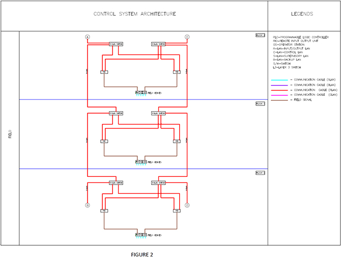
For a given process block, the RIO’s are distributed in the field at various elevations. Each elevation houses a network cabinet with redundant R-LAN switches. The RIO’s are connected to the redundant R-LAN switches of that elevation. The redundant R-LAN switches of the various elevations are connected in a daisy chain fashion and form a ring network with the R-LAN switches in SCR & MCR. This is depicted in Figure 2 of the Control system architecture for better clarity.
Overall Control System for the entire plant is formed by interconnecting dedicated systems of each process block. The control systems of these process blocks interconnect the C-LAN & S-LAN with layer-3 network switches. These layer-3 networks will be used to exchange the process data between process blocks.
Certain critical process monitoring and operations are facilitated through a Backup system, apart from being monitored and controlled by the main PLC. This backup PLC is located in the field of each process unit. The purpose of backup system is to increase the availability of the critical parameters and their control. The backup system comprises of the major components like backup PLC, backup SCADA, video graphic recorder, alarm annunciator etc. The backup system network is completely independent of the main Control system network. Each process block has its own backup system network.
POSSIBLE FAILURES AND THEIR EFFECT ON PLANT SAFETY
The eccentricity of the control system envisaged in each process unit of the plant is that the redundant processors, servers, operator stations, Ethernet Switches etc., are physically separated from the associated main components. All the main components/subsystems of the control system are located in the main control room and all the redundant components /subsystems of the control system are located in the secondary control room of the respective process Block.
With reference to the Control system architecture, the postulated failures are analyzed considering that the plant is normally operated form the Main Control Room.
- When the active SCADA server/PLC located in the Main Control Room fails the standby SCADA server/PLC located in the Secondary Control Room will take up the control and carry out their respective functions.
- When one operator station fails, the section of the plant being monitored by that operator station will be assigned to any other operator station to carry out the monitoring and control. When all the operator stations in the Main control room fail, the control and monitoring of the process will be done from the operator stations in the secondary control room of the respective process block.
- Redundant ethernet switches/Communication links are considered in the Main Control Room and secondary control room at all three communication levels (R-LAN, C-LAN and S-LAN). Within the Control room when the main Ethernet switch/communication link fails, the redundant ethernet switch/communication link will still be available, thereby increasing the availability of the subsystems (PLC, SCADA, Operator stations) within the control room.
- When the redundant ethernet switches /communication links of the R-LAN located in the network panel of the rack room fails, it results in loss of data from that particular set of RIO’s located in that floor. Under this condition, modules in the failed RIO rack are pre configured to go to fail safe state. Failure of the redundant ethernet switches/communication links of the R- LAN in Main Control Room, results in the failure of the main PLC. Hence changeover of the main PLC to the redundant PLC takes place.
- When the redundant ethernet switches/communication links of the Control LAN in Main Control Room fails it results in the failure of the main PLC and SCADA. Hence changeover of the PLC and server from the main to the redundant takes place.
- When the redundant ethernet switches/communication links of the supervisory LAN in Main Control Room fails it results in the failure of the main SCADA and all the operator stations in the Main Control Room. Hence changeover of the server from the main server to the redundant server and the entire control and monitoring will be done from the Secondary Control Room operator stations.
- In addition to the above redundancy at component levels, critical parameters in each process unit are multiplied and taken to an independent PLC, one each housed in the SCR & MCR respectively. The data is logged on Video graphic recorders and annunciators in both the SCR & MCR. Operation of the plant will be through redundant backup Operator work stations housed in both SCR & MCR. Hence redundancy in provided in the backup system.
- Failure of both the SCADA Servers/PLC CPU’s or total failure of all the R-LAN,C-LAN and S-LAN switches and communication links , the PLC mode will not be available and the mode of operation will be changed over to Backup MODE automatically and all the running operations will be switched off safely. In Backup MODE of operation, selected critical devices can be operated from the Backup System network. Recorders are available as Backup for monitoring of process parameters and hard wired Alarm Annunciation system is available as a Backup for alarms.
Suppliers such as Siemens, Schneider, ABB offer such physically separated redundant processors.